HOWTO: The OSADL Parport Monitor
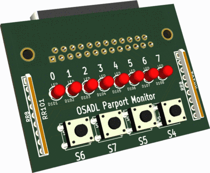
It sometimes is required to directly signal a computer state at an output port without using a driver, e.g. in a crashed system that is no longer able to handle interrupts but still has some kind of life in it. The parallel port is ideally suitable for this purpose. A simple DB25 plug with LEDs to monitor its output bits is described here.
Ordering information
If you don't have the time to build your own device using the below manufacturing data, order one that is assembled and ready for immediate use. It is available at Amazon, and we always have a certain number of them in stock. Click here to place your order.
A simple schematic

![]() Open Source KiCad EDA Software Suite.
Open Source KiCad EDA Software Suite.
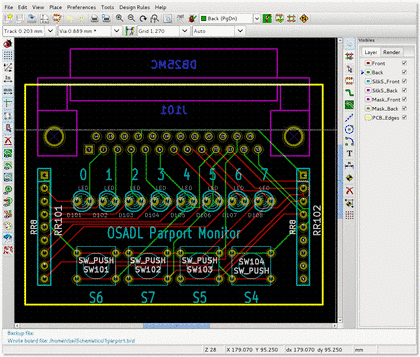
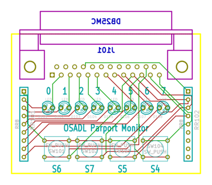
Below is a link to the schematics in PDF format; in addition, a screen hardcopy and some intermediate images of the KiCAD application are shown. Finally, all Excellion and Gerber files are provided that may be sent to a professional PCB manufacturer. Alternatively, ready-to-use assembled Parallel Port Monitors can be obtained from OSADL.
Related kernel patch
Many systems of the OSADL QA Farm are equipped with this device; here is a kernel patch that exemplifies how the parallel port may be used to monitor NMI activity. This feature may help to determine whether there still are some embers in the ashes of a crashed system. Another functionality allows to output the number of the most recent system call, hardware IRQ or software IRQ vector as additional hint in a post-mortem diagnosis of a system crash.
Download the schematics of the OSADL Parport Monitor
Schematics of the OSADL Parport Monitor (PDF format) | 20 K |
From schematics to PCB with KiCAD
3D image of PCB only
3D image of fully populated board
KiCAD board file
This file can be loaded directly into KiCAD | 28 K |
Some additional components used in the parport project | 119 K |
Excellon and Gerber files to submit to a PCB manufacturer
Drill commands | 1.5 K |
Front circuit | 3.7 K |
Back circuit | 3.7 K |
Front mask | 2.0 K |
Back mask | 1.7 K |
Silk Front | 71 K |
PCB edges | 434 |
Related kernel patch of setparport module
add-nmi-callback-and-raw-parport-driver.patch Setparport module | 18.8 K |


